 Shop Online
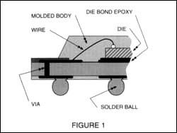
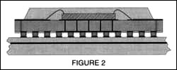
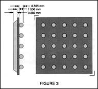
Motorola OMPAC C-5 BGA Removal and ReplacementThe Motorola OMPAC represents the state of the art in surface mounted IC chip technology. Although it has some elements in common with traditional leaded QFP and PLCC chip components, it is nonetheless significantly different in some major ways. For example, the OMPAC chip’s interconnects to the circuit board are completely beneath the chip, as opposed to being on the outer edges, as with a QFP or a PLCC. The first illustration, Figure 1, show a cut-away view of a typical OMPAC; Figure 2 shows a PLCC. Like other chip components such as PLCCs or QFPs, it contains an integrated circuit (die) with connections to the exterior so that it can be soldered (physically and electrically connected) to a circuit assembly. Unlike other leaded components, however, its connections to the circuit board or assembly are contained entirely under the body of the chip and are made by a grid-like array of solder balls, hence the term Ball Grid Array or BGA, the proper term for this type of chip component. Once installed, BGAs have no outwardly visible connections to the board, but surprisingly, they are relatively simple to remove and replace using the correct procedures with the appropriate equipment. In addition, the BGA chip itself has very little mass compared to other components of comparable lead connections, like large QFPs, so they must be heated and processed more gently and carefully than traditional large chip components. OMPAC chips can be sensitive to moisture, and are therefore packaged, when new, in sealed containers. When in service or exposed to the environment for any length of time, the may absorb moisture, and if heated too rapidly, can “popcorn” and delaminate. For defective OMPACs about to be removed from a circuit board, this is not a concern; however, new OMPACs should not be removed from their containers until ready for installation. Table 1 shows the allowable time that different components with different moisture sensitivity levels can be exposed to air before baking is necessary prior to soldering. Sometimes it is desirable to remove a “good” OMPAC chip from a “bad” board, or protect a “good” board and its other components-such as adjacent OMPACs-from “popcorning” if it has been in a high-humidity environment. In such cases, the circuit board should be pre-baked to drive out any moisture prior to rework. A special nozzle for this purpose has been designed for the Chipmaster, Motorola oven nozzle, part number 01-80303E15. Otherwise, a temperature-controlled oven designed for drying and baking circuitry will be adequate. The chart (Table 2) will show what baking times at 125° will yield process “windows” during which time the OMPAC chip should be reworked: The controlled, gentle heating ramp rate of the Chipmaster ensures that “popcorning” or other thermally induced adjacent component damage will not occur or be a concern. Replacement OMPACs readily self-align on their pads due to the surface tension of the solder. As long as the OMPAC has been located with a fair amount of precision and care, it will self-align once the solder balls underneath become liquid, during heating. The circuit board itself has been marked with guide lines to facilitate correct alignment by the operator. Figure 3 shows the pattern of connection for an OMPAC BGA, including alignment guides as marked on the circuit board. The illustration shows how much misalignment is acceptable-much more than would be allowable with a typical QFP. In addition to the BGAs self-alignment qualities, the solder balls supplied with the BGA provide the correct amount of solder for a perfect solder joint, so no additional solder need be applied to the board prior to replacement. OMPAC Removal Procedure 1. Flood the area under the component or “chip” to be removed with wetting solution, Motorola Part #66-80333 E73 prior to component removal using the “eye dropper” found in the Motorola SMD ToolKit (Motorola Part Number 01-80303 E45); Figure 4 illustrates the correct application method. 2. Set the temperature control on the Chipmaster to 425°. Reset the timer to zero. To set or change setpoint temperature, press the INDEX key on the controller TWICE; then press either the “UP” or “DOWN” arrow to reach the desired temperature (RED LED display). To do this, use the “UP” arrow to increase; hold the button in to increase rapidly. To increase temperature in one-degree increments, press the arrow button in individual steps. The same procedure works for the “DOWN” arrow button. Then press ENTER. Press the INDEX key one more time to return to the operational menu. 3. To reset the timer to zero, press the ENTER key and the “DOWN” arrow key simultaneously. The display will flash once, indicating that the timer has been reset to zero. How the Timer Works: When the specific time has been set, e.g., 60 seconds, the Chipmaster’s timer counts down to zero once the foot pedal to start the heating cycle is depressed. The timer will stop at zero, even if the heating continues (foot remains on the pedal). If the timer is reset to zero, it will begin counting UP once the heating cycle begins and will STOP counting once the cycle is stopped by the operator (foot pedal released). The timer will display the cycle time (e.g., 45 seconds). Each time the foot pedal is depressed to start the cycle thereafter, the timer will count DOWN to zero from whatever that cycle time (in this example, 45 seconds) was recorded. The procedure for changing cycle time is similar to setting temperature. 4. To Set Time: Press the INDEX key ONCE (from the operational menu) to reach the timer set menu. Use the “UP” arrow key to increase time in one-second increments; hold the button down to increase rapidly. Once the time is set, press ENTER; then press the INDEX key TWICE to return to the operational menu. 5. Install the appropriate nozzle in the Chipmaster. The nozzle orifice should be only slightly larger than the chip itself. Center the chip under the nozzle as shown in Figure 5. Be sure to observe vent and height positioning as shown in Figure 6. 6. Depress the foot pedal to begin the heating cycle. Note that the GREEN display will begin “counting” the seconds while heating. The RED display will indicate the heated air temperature as it ramps. 7. Turn on the vacuum pump, then depress the vacuum pickup assembly to capture the chip. The chip will not, however, lift off at this time. CAUTION: After removal, do not touch or move the chip! 8. After 40-60 seconds of heat application, observe the vacuum pickup assembly. It should lift up automatically with the chip held be the suction cup. This lift-off indicates that the chip has been successfully removed. 9. Remove the board holder arm assembly from under the nozzle, but DO NOT turn off the vacuum or move the chip. 10. Leave the chip in position until the RED LED temperature indicator (nozzle temp.) drops to 300°F. 11. Using tweezers in the Motorola SMD Tool Kit, grad the cooled chip and turn off the vacuum pump, using the switch on the front of the Chipmaster. Replacement Prep The OMPAC chip is supplied with solder balls, engineered to make perfect solder joints. No additional solder need be added to the pads; however, leftover solder on the pads/board must be removed completely, and the pad should be smooth, clean and tinned. 1. Use a soldering iron in conjunction with the wick gun-Motorola part number 66-80333E70 (as shown in Figure 7) to remove all residual solder from the pads of the chip area leaving clean and tinned pads. Do not use excessive heat or pressure, because pad damage and/or removal could result. If the pads are not smooth and shiny, use the hot air reflow procedure which follows to clean them. If the pads are acceptably clean and ready for reattachment, add a drop or two of the wetting solution directly on the pad area and proceed to the Replacement Procedure.
Replacement Procedure 1. hot air level the pads if needed. In most instances, sufficient tinning will remain on the pads to attach a new chip; but the surface may be rough, uneven, or have solder “icicles”, making accurate placement of a new chip difficult. To hot air level, first place a drop or two of wetting solution on the pads. Then depress the foot pedal of the Chipmaster to initiate the heating cycle. The GREEN display will begin counting DOWN to zero. The solder will melt and become smooth; the solder should cover the pads completely and have a shiny appearance. 2. Remove the board and board holder assembly from beneath the Chipmaster nozzle (depress cylinder, slide holder and board out). Let the board cool to ambient temperature. 3. Next, apply a thin layer of no-clean flux paste to the OMPAC bonding area, so that the paste is evenly brushed and spread over the approximately 1/2 square area as shown in Figure 8. Pick up a replacement chip using the aforementioned tweezers from the SMD Tool Kit then place and center the OMPAC chip on the pads, within the boundaries of the registration lines marked on the board (again, refer to Figure 3). Make sure the chip has been placed as accurately as possible and the outer edges of the package are in proper registration with the site. 4. Carefully place the board under the Chipmaster and align the OMPAC chip with the bottom of the nozzle in the same manner as was done for removal. Center the component under the nozzle as accurately as possible. 5. Press the INDEX key on the Chipmaster controller ONCE and verify or enter the appropriate cycle time. The appropriate cycle time for reinstallation is the same as the removal time plus 30 second, to ensure good solder wetting.
6. Depress the foot pedal to begin the heating cycle, hold down until the timer reaches zero. 7. Release the foot pedal to end the heating cycle and, after the RED temperature LED indicates 140°F, remove the board from the Chipmaster work area.
|


Like Us


